How to Create the Network Topology in MATLAB
I have seen candidates struggling with the basic step of network simulation. Yes, I’m talking about creating a network topology. As discussed with a number of computer science researchers, I have found that many of them are confused regarding the topologies, such as selecting the software (NS2 or MATLAB) for topology creation, creating the static or dynamic topology, the number of node in a topology, number of connected nodes and many others.
Throughout my consulting career, I always wanted to be a help for research candidates, and today, I have decided to help them with the network topology.
Okay, let’s start this by asking:
What is a Network Topology?
I would like to go with the simplest answer; a Network Topology is a schematic arrangement of nodes and connecting lines (edges). There are two ways to define a topology:
i. Physical
ii. Logical
What is the logical way to represent the topology in MATLAB?
A network topology can be representing logically in the form of a Graph.
A graph is a collection of nodes and edges that represent relationships among different nodes or you can among different vertices or objects.
- Nodes are vertices (weighted or non-weighted) that correspond to objects.
- Edges are the connection lines between objects (vertices).
- The graph edges sometimes have Weights, which indicate the strength (or some other attribute) of each connection between the nodes. For example: In case of network routing weight represents the distance between the different nodes.
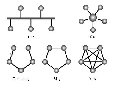 Fig. 1: Type of Topology
Now, moving to the most important question, i.e.
How to create the network topology using MATLAB?
In MATLAB creating a topology requires developing a graph that can be both undirected and directed graph.
Undirected Graph: This type of graph has nodes connected with edges. The edges have no direction and indicated a two way relationship that means each edge can be traversed in both directions.
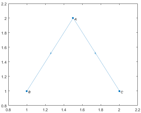
Fig. 2: Undirected Graph
Directed Graph: A directed graph is a combination of nodes and connected edges with direction. The edges indicate one-way relationship, each edge can only be traversed in a single-direction.
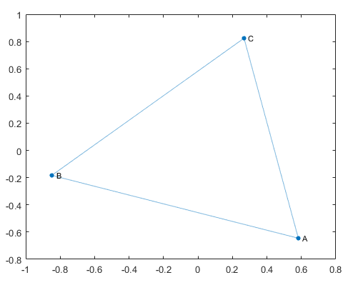
Fig. 3: Directed Graph
Creating a Graph:
Adjacency matrix is the best way to implement a graph in MATLAB. The matrix is the combination rows and columns. In an adjacency matrix, the non-zero entries represent an edge between two nodes.
For example: We have to create a topology for nodes weighted as:
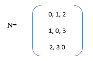
To create the graph, provide the follow input in MATLAB workplace:
A= [0 1 2; 1 0 3; 2 3 0];
node_name = {‘A’, ‘B’, ‘C’};
G= graph (A, node_names)
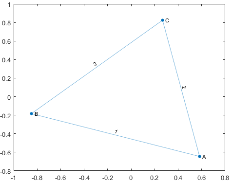
Fig: Weighted Undirected Graph
Now, represent the graph using edge list:
Edge Weight
(A, B) 1 (A, C) 2 (B, C) 3
The edge list in the MATLAB is separated by column into source nodes and target nodes.
source_nodes = {‘A’, ‘A’, ‘B’}; target_nodes = {‘B’, ‘C’, ‘C’}; edge_weights = [1 2 3];
G = graph(source_nodes, target_nodes, edge_weights)
You can also construct the graph by creating the table with appropriate variables.
EdgeTable = table({'A' 'B'; 'A' 'C'; 'B' 'C'},[1 2 3]', ...
'VariableNames',{'EndNodes','Weight'});
G = graph(EdgeTable)
You can also modify the existing graph and can add variety of functions to the topology by using the following commands:
| addedge | Add one or more edges to the graph |
| rmedge | Remove one or more edge from the graph |
| addnode | Add one or more nodes to the graph |
| rmnode | Remove one or more node from the graph |
| findnode | Locate a specific node in the graph |
| findedge | Locate a specific edge in the graph |
| numnode | Find the number of nodes in a graph |
| subgraph | Extract Subgraph |
If you still have any confusion regarding the same, kindly post your comments below!